By: Chad Zentz
In this how-to I will show you how to install a DCC board in the IMRC SD40-2W.
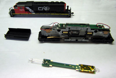
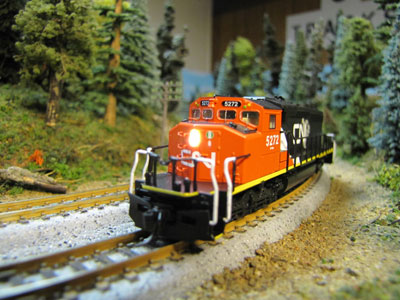
First a quick review of the locomotive itself.
I find this to be a very nice loco out of the box. IMRC did a great job with the detail. There are individual grab irons installed, windshield wipers installed. Colored class lights (non-operateing) above the number boards. It also has the single rear headlight as per the prototype. The paint is nice and crisp. The handrails are a little thick but not bad. The paint and plastic on the front of the nose is thin enough that you will want to remove the shell and paint the inside of the nose black around the light lens as the light shows through and the whole nose glows red if you don’t. The mechanism seems to be consistent as I have 3 of these units and all run well but have just a slight gear noise. This seems to get better as they are run. The side cab windows seem a little small but if you look at prototype photo’s I think you will see they are a little smaller also. It also comes with Micro-Train couplers installed and a snowplow.
The inside of the loco is a split frame that is secured with 3 screws, one above each truck and one on the lower portion of the area where the fuel tank resides. The nose lights are two Surface Mounted LED’s (SMLED) attached to a PC board that is screwed to one of the frame halves. Two wires from this PC board run up to the main PC board on the top of the frame. I think this is a poor design hence part of the difficulty in the DCC installation. With Kato using light piping for nose and ditch lights I feel IMRC rushed this part of the development. As far as the ditch lights are concerned they are non operating but are prototypical in appearance.
Over all I like this model as I have 3 and feel the short comings are not a deal breaker.
Now for the DCC installation.
You will need the following, 1 Small Phillips head jewel type screwdriver, a soldering iron, some black electrical tape or the thin yellow Kapton tape, black paint (your choice) and about 15-20 min. to complete
I have used both the NCE (N12A0e) and Digitrax (DN163IO) boards in these loco’s and find the Digitrax (DN163IO) is the better and easier board to use. This is due to the placement of the LEDs. On the NCE the front and rear LED’s are right on the edge of the board. Both need to be removed and a new rear LED with longer tabs needs to be added. This also causes concern with the potential to damage the NCE board durring the LED removal. On the Digitrax there is a long LED is on the front of the board which is convenient as the front LED need to be removed anyway as you will see in the accompanying photos. You won’t need to modify the rear LED as it sits in the correct spot and is clearly visible through the rear headlight.
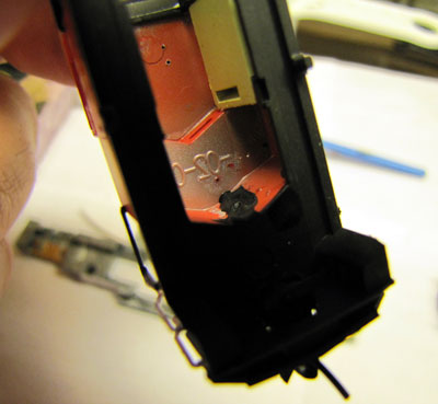
1. First step is to remove the shell by gently tapping the ends against the edge of a workbench or table. Be careful not to break the snowplow off. Then remove the fuel tank. I would at this point paint the inside of the nose black so it can dry while you continue with the installation.
2. Next, remove the 3 screws. One over each truck and one in the fuel tank area then gently separate the frame halves.
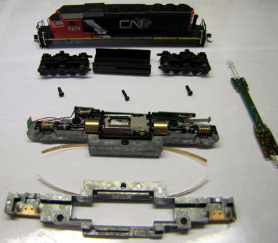
3. Now unsolder the 2 nose light wires from the main PC board (the one in the top of the frame) then remove the PC board.
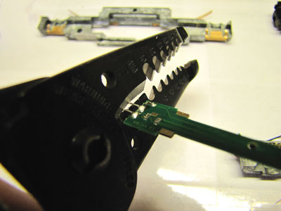
4. Now take the DCC board and cut the long LED off leaving about 1/4 ” of the two prongs or if your comfortable enough remove the LED completely from the board.
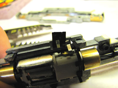
5. Next take the motor leads and bend the tips up slightly so they go into the two slots on the DCC board. Take a piece of electrical tape or the Kapton tape and place a piece around the frame by where the lower motor lead comes up. This is just a precaution as to not short out the board. Place the DCC board in the frame half with the motor making sure the motor tabs go into the slots in the middle of the board.
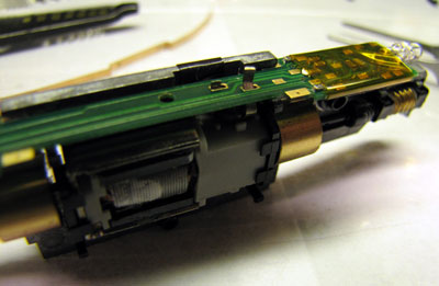
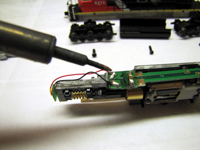
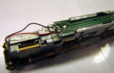
6. Now solder the two Nose light wires to the prongs you left or directly to the board. See photo for wire placement. If the front of the loco and board is to the left, the red wire will need to be soldered closest to you and the black wire furthest away.
7. Now make sure the worm gears and bushings are set in the correct position in the frame and assemble the frame halves.
8. Place the trucks back in the frame and confirm the copper strips contact the brass contact tabs on the trucks. Screw the halves together and place on a test track or on the layout to test. Your factory default address should be 3. Test motor and light function.
9. If all is well, replace the fuel tank and shell and your ready to program the loco and take her for a spin on your layout.
I hope this has been a helpful and informative review and how-to.
Thanks , Chad