By Glenn Roberts
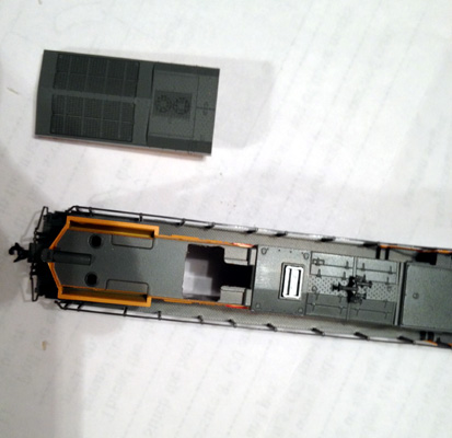
My installation reflects closely what was in the Digitrax manual. The
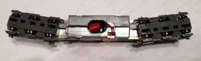
speaker is located in the rear and the capacitor is in the fuel tank area.
This can be seen in pictures 1 and 2.
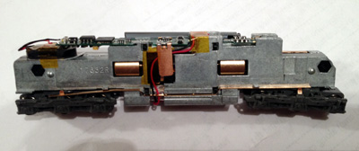
One thing that can be seen as a deviation is that the wires for the capacitor are run under the circuit
board power clip and down the side of the fuel tank. A 1/8” end mill was
used to cut the shallow grove used to get the wires to the power clip area.
The ear at the top near the circuit board was also milled back approximately
1/8”. The edge was slightly rounded with a file creating a smooth transition
for the wires to travel over the edge.
My other deviation can be seen where the capacitor wires run down the side
of the fuel tank. The wires travel behind the brass pickup strip. A 3/16”
end mill was used for this groove. The grove is just deep enough for the
wires and slight clearance. Care was taken to locate the groove between the
plastic motor mount tab and the dimple in the brass pickup strip that helps
hold the strip into the frame.
When you look at picture 2 it shows a groove leading to the capacitor
cutout. This groove was also made using a 3/16” end mill. The corner leading
from the side of the frame to the bottom groove was also rounded with a file
to create a smooth transition for the capacitor wires. The capacitor cutout
was made using a 5/16” end mill and the cutout goes through the frame into
the motor area. The frame insulating bushings were not in place when the
cutout was made which makes cutout the slightly wider than 5/16” after
assembling the frame with the insulating bushings in place. One thing that
cannot be seen is that the bottom strap of the plastic motor mount has a
portion cut away to allow the capacitor to fit completely into the cutout.
The fuel tank cover fits nicely by doing this and didn’t need to be trimmed.
The only other modifications done to the frame was to mill away the
triangular protrusions at the end of the frame where the speaker is located.
A file was actually used for this process.
The next process was to modify the shell to provide clearances for the newly
added circuit board. This was a point of frustration but the modifications
are fairly simple after learning what exactly needs to be done.
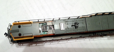
One point of interference that was discovered was the two chips just in
front of the circuit board power clips. The two chips are just slightly high
and can be seen in image 3.
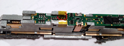
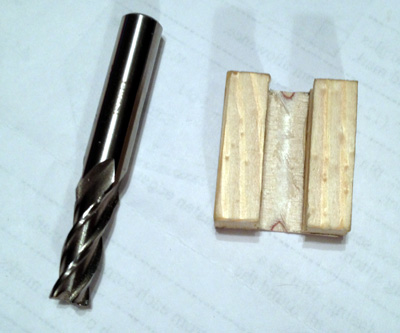
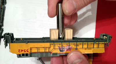
To fix this problem a fixture was made
using two 3/8” square pieces of wood 1-¼” long glued to a 1/16” piece of
plywood. The two 3/8” square pieces of wood were spaced 3/8” apart using a
3/8” end mill. The fixture can be seen in image 4.
By inserting the
fixture into the shell and using the 3/8” end mill turned by hand a slight
amount of the shell can be faced off to provide clearance for the two chips.
This process can be seen in image 5.
Only a slight amount needed to be
removed. This is a tight area for the GEVO shell and this is also the reason
the capacitor wires were routed over the side of the frame instead of
between the circuit board power clips and then over the side.
Another point of shell interference was found with another chip in the
radiator area. To fix this problem the radiator was removed from the shell
and a cutout was added near where the radiator latch engages the shell. This
cutout can be seen in image 6 and in image 7 which shows the shell
placed on the frame.
One last thing that had to be done in this area was
that the speaker needed to be slightly narrowed with a file allowing it to
slip nicely into the shell.
A couple of other shells were also test-fit to this frame. The Kato SD70M
shell fit right on this particular frame without any modifications. The Kato
C44-9W shell needs modifications to fit this particular frame. The problem
with the C44-9W shell is that the chip causing interference in the radiator
area is right on the radiator latch tab. This problem might require gluing
the radiator on due to removing the latch. Care would also need to be used
in removing material from the shell just in front of the radiator latch.
This would be a thin area after removing the proper amount of material. The
exhaust stack also hangs down into the shell of the C44-9W and some of it
also may also need to be removed. I believe the AC4400 radiator is the same
as used on the C44-9W. The same fixes should apply.
I hope this information will be useful to others.
Best Regards,
Glenn Roberts