By: Mike Fifer
There has been a lot of discussion since the latest run of the lifelike N Scale GP20 has been released about the fact that there is not a drop-in decoder on the market for these locomotives currently. I simply could not wait around for someone to come up with one so I wired in a TCS Z2 decoder to the existing circuit board. In the following text is how it was done.
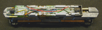
You first have to remove the shell by gently pulling upwards to expose the raw frame. The existing circuit board and frame are shown below.
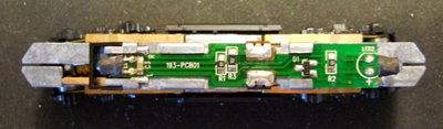
Now to remove the circuit board you simply put your thumb in the middle of it and slide it backwards and lift up slightly at the rear of the board. Once the board is set aside I placed a piece of Kapton tape on the rear of the frame as well as where the motor tabs drop down to the motor contacts. This is simply a precautionary measure.
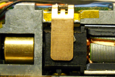
The picture below simply shows the relative size of Z2 as it will sit under the circuit board.
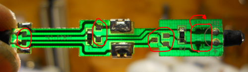
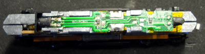
In the picture below you will see four red circles. These circles show the components that need to be de-soldered and removed from the board. The circle on the far right is for the two components on the bottom side of the board. A couple of these components do not necessarily need to be re-removed however I removed them for cleanliness on the board.
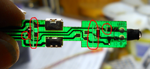
In the following picture you will see the locations where the board traces need to be severed using the tip of a hobby knife. Please study this closely because if you do not make all of these cuts it is possible to burn the decoder out. As you can see the two cuts in the center of the board sever all ties all the way across the board and the two outer ends simply sever one lead to each LED.
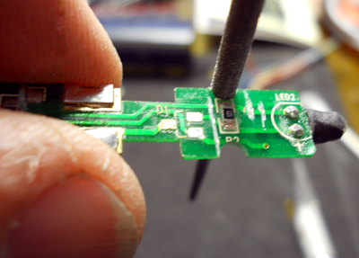
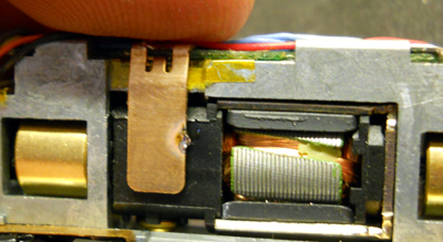
Once the cuts are made and the board is cleaned of the un-needed components the next step is to file two circular cuts into the edge of the board adjacent to each side of the rear LED resistor is shown below. This will allow the wires on each side of the decoder to come up on top of the board without affecting the placement of the shell. Once the notches are made the board can be slid back into place on the chassis and the decoder can be slid under the rear LED.
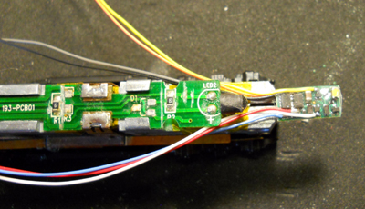
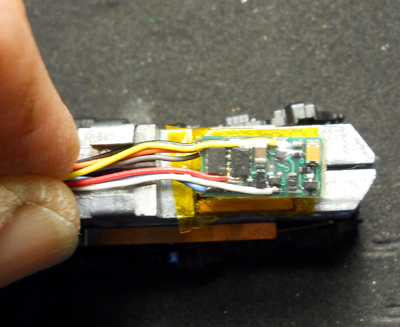
Once the decoder is slid under the rear of the circuit board the wires are routed to each side and up over onto the top of the board.
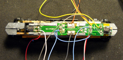
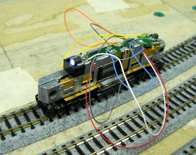
Whenever I install a wired in decoder I always start by leaving all of the wires their full length and soldering them where they belong so that the locomotive can be tested and if a problem arises it is much easier to de-solder it and make changes. So what you see below is what I do and shows the proper location for the soldering of each color wire and its point on the board. I then take the locomotive to the test track and make sure that the decoder works and the lights function properly. After this is done I take the locomotive back to the bench and dress all the wires to the proper length and re-solder them for a tailored fit.
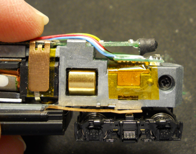
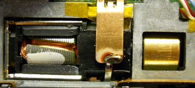
At this point were almost done but to ensure a proper motor connection I pull the motor tab that comes from the top of the motor out to the side of the pickup tab on the circuit board so I can solder it together and I then go around to the other side and solder the lower tab on the motor to the pickup tab on the circuit board. This will ensure that no corrosion will take place and hamper the operation of the decoder in the future.
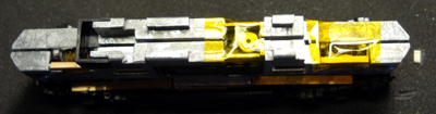
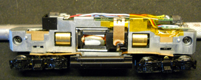
Now if you have made it this far this is what your completed chassis should look like.
Now take the chassis back to the test track and reconfirm that everything is working properly. Once that is done all that’s left is to snap the shell back on and have fun with the new DCC equipped GP 20.