By: Mike Fifer
When I started my layout I decided to use the Kato turnout control switches as part of a package product and they work well but they are highly visible and relatively large to install around the layout.
As many do I started looking around for an alternative when I built the new control panels. What we first must know is that the Kato turnout control switches are not twin coil but rather DC polarity controlled. This means that instead of two push buttons one to activate a coil on one side and another push button to activate a coil on the other side to pull the switch machine back one has to reverse the DC polarity of the coil to push and pull the turnout control. This requires a double pole double throw momentary on off on switch and in this how-to I will show you how to wire one of those up and where to get them.
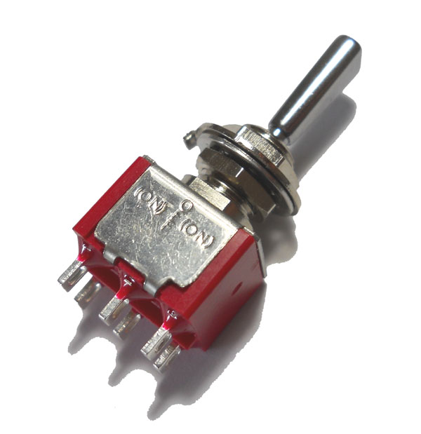
I started with one of our double pole double throw momentary switches located here. These are high quality switches at a reasonable price. The switches also have a flattened throw handle which makes them easy to distinguish between the turnout controls and the block switches which have round handles on my panel. Below is what the switch looks like.
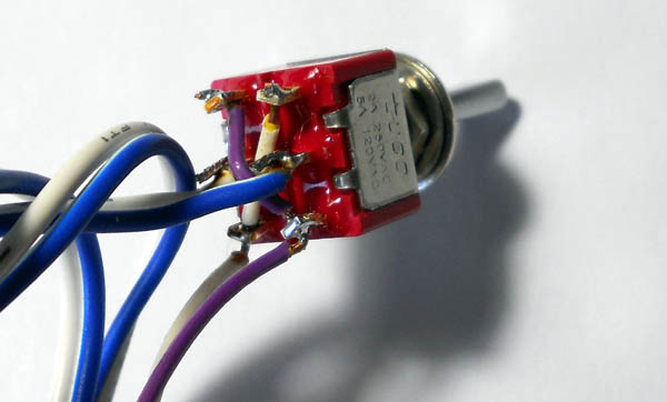
Wiring this switch for use is very easy. It first requires that you solder a wire from each corner to the opposite corners in an X pattern which serves to reverse the polarity when the switch is thrown in either direction.
Note: the X pattern wires cannot touch each other as a short will occur in your power supply so they must be insulated wire.
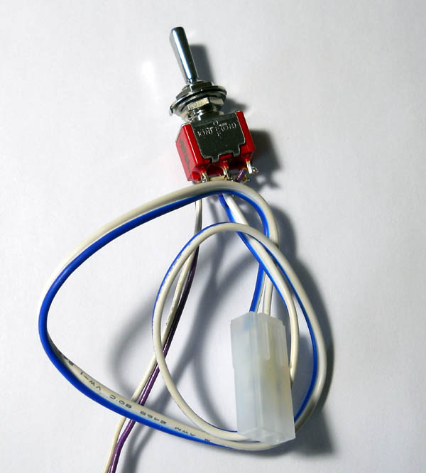
The next step is to solder the wires to your turnout to the two center tabs. And the final step is to solder your incoming power to either end of the switch attaching them to your X pattern. On my last photo you will notice that I have put the Kato turnout control wire with a plug on my two center positions so the turnout could just be plugged into the switch, this is not necessary but it was just to show that it could be done if you choose.
Note: after these are installed and if the turnout operates in the incorrect direction you can either rotate the switch upside down or re-solder the incoming power leads opposite the way you have them to correct this issue.
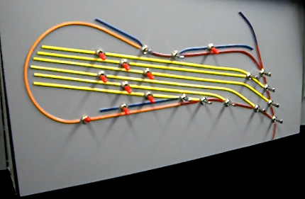
These switches require a quarter inch hole to be drilled in your panel for mounting purposes. Once the switches are wired in they operate flawlessly. Below is how my finished control panel looks and if you’re interested in how I made this control panel Fifer hobby supply has a how-to video available here.