By: Jeff Whitehorn
I am seeing more and more comments on the internet recommending that owners of Kato F3, F7 and E8/9 diesels solder the motor tabs to the decoders, rather than using those (admittedly) pesky gray clips to hold the board down and force a connection to the decoder. As the Quality Manager of an electronic assembly company, I cringe every time I see this being recommended.
Why would I recommend against it? Two simple words: intermetallic growth. When a solder joint is made, the two metals involved, such as tin in the solder and copper in the pad, become alloyed in a very thin layer, which is a mixture of the two metals (in this case, bronze). This intermetallic layer should be as thin as possible, as it is not as conductive as the other materials. The same thing happens inside an integrated circuit; tiny wires are bonded to the silicon chip, usually a gold wire to an aluminum pad. Once again, you want this layer to be as thin as possible, because it is not as conductive as the original materials. Chip designers call this layer “The Purple Plague”. Why is this necessary layer so maligned?
Here is the bad news. The soldering or bonding process has started a chemical reaction. Eventually, this layer will grow until it has consumed the entire joint. On your Grandfather’s old vacuum tube radio, with its analog signal, this didn’t hurt the performance much. To digital electronics, it is fatal. Eventually, all modern digital electronics will fail for this reason, due to this layer growing too thick to pass digital signals adequately. The process may take years, or decades, but it is as inevitable as the sun rising.
So what has this to do with soldering decoders? Here is the worse news. Heat speeds up the growth process of the intermetallic layer. That is why additional soldering, if not done correctly, can introduce a latent failure…in other words, it will work for a while, but it is doomed to a much shorter working life. I have seen soldered decoders “go dead” within a matter of weeks.
What to Do?
I could write an article on soldering techniques that reduce heat damage, and I just might at a later time. But my recommendation is that you use the gray clip instead. Don’t get me wrong; I’ve chased my share of those little tyrants across the floor. But after a few successful installations, I have found out how to make those pesky clips perform the way they were designed. I will outline this process step by step in this article.
Materials you will need
You will need a type of tape, yellow and semi- transparent in appearance, called “Kapton” tape. It is used in the electronics industry for its insulating ability and resistance to heat. The good news for us is that it is also very thin. If you’re using common electrical tape to insulate the pickup springs from the motor tabs, you will never get the decoder to sit flush enough; that is why the clips don’t seat well. Before you panic because your local electronics store doesn’t have Kapton tape, try going HERE. With a little advance planning, you will have a roll in your hand and ready to install in short order. The width you want is 6mm, or ¼ inch. One roll is a lifetime supply…I have installed decoders in nine locomotives so far with the roll I have, without even making a dent in the roll.
You will also need toothpicks (four with undamaged ends, the old fashioned round wood kind), scissors that are fairly sharp (any length), and a hobby knife or small screwdriver. Tweezers or needle nose pliers may help on the pickup springs, but DO NOT use them on the clip.
Installing the Decoder
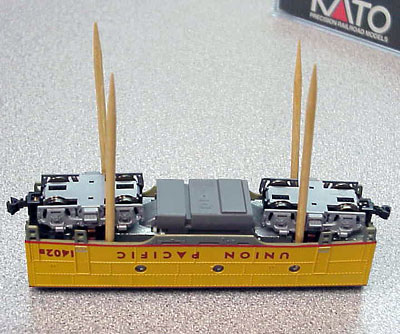
The first step is to remove the shell. You can do this by placing the toothpicks between the shell and the chassis, which will move the shell away from the detents. The location shown in the first photo is for “F” units. E units require the toothpicks to be placed at the inside end of the trucks. Gently lift the shell from the back end first. If it does not come apart easily, move the toothpicks and try again. DO NOT FORCE IT. Damage to details on the shell or truck side frames may result.
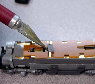
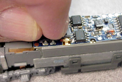
You will find a small circuit board, held down by the infamous grey clip . Gently pry the clip up with the end of a screwdriver or hobby knife, being careful to not let it flip through the air and land somewhere where you will have to search for it. A warning…do not, at any point, handle the clip with tweezers, needle-nose pliers, etc., because the slippery plastic these clips are made of will squeeze-fire just like a watermelon seed. Set it aside in a dish or somewhere where it won’t get lost.
The two motor tabs are folded somewhat over the circuit board. Bend them straight up, but not beyond vertical. With a small pointed marker, mark the tops of the springs next to the motor tabs. You may want to draw little arrows, pointing toward the centerline of the locomotive. Carefully, so as not to bend or distort the springs, remove them. Tweezers or needle nose pliers may be helpful here, but take great care not to damage the springs.
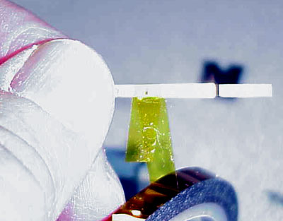
The next part is where the Kapton tape comes in. The pickup springs, which used to make contact with the motor tabs for DC operation, must be insulated so that current picked up from the track will go through the decoder before it gets to the motor tabs. To do this, peel about an inch or so from the roll of tape, being careful to avoid getting your finger oils on all but the end, pass it on the underside of the spring (adhesive side up), around the edge that faces the outside of the locomotive, and on top. RESIST the temptation to keep wrapping. Leave the edge facing the centerline of the loco unwrapped.
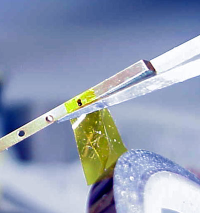
Use a pair of sharp scissors to cut the tape right next to the spring . Do the same on the other spring. Remember, the wrapping on the two springs will be mirror images of each other. That’s where drawing arrows may help you to keep track.
Now, gently place the springs back where they started . Remember, three of the four sides on the spring have tape on them. The edge facing the motor tab must be insulated, or there is a good chance it will make contact with the tab when it is bent back down. Wrapping all four sides would make it difficult to get the spring back into place. Be careful to locate the hole in the center of the spring over the tiny plastic post. The sharp edges of the sheet metal inside this hole can shave the post and turn it into a thick stump. On the “F” locos, you will have to carefully maneuver the spring ends into the end “pockets” before seating the springs.
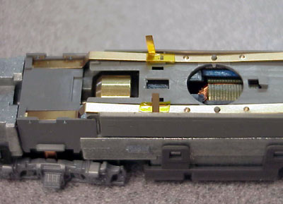
Gently press downward over the taped area with the point of a small screwdriver of needle nose pliers, so that the spring fits down into the slot formed by the side of the frame and the short “wall” on the plastic chassis. The springs tend to jump back up, but be patient until you get both fully seated in place against the plastic. You will find that the thickness of the tape will actually help wedge the spring in place. Make sure that the bottom side of both springs are flush against the plastic, where the tape is.
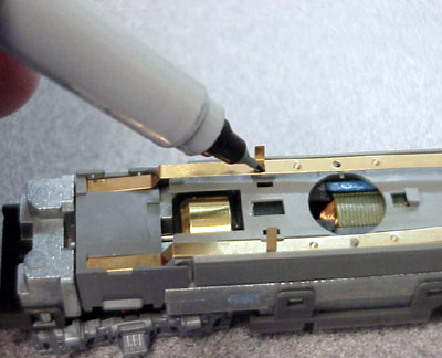
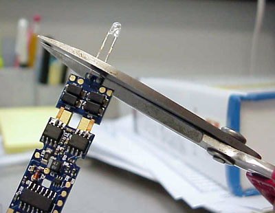
Now comes the decoder. IMPORTANT! Touch a grounding source before you take the decoder out of its bag. The screw on a nearby outlet plate will serve fine. Take the decoder out of the bag, flip it over, and bend the little pickup tabs to a 45 degree angle. If installing in a “B” unit, cut off the LED .
Now flip it back over again and carefully place the decoder where the circuit board was on the chassis, putting the little grey hook on the chassis into the corresponding hole on the decoder and sliding the decoder back until it stops. Gently align the decoder so that it fits into the same recess the circuit board was in. BE VERY CAREFUL NOT TO BEND THE DECODER. Damage to the traces or solder joints may result.
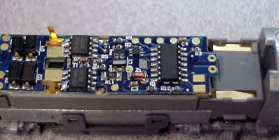
Now, fold the motor pickup tabs down as they were when you removed the clip. Pick up the clip with your fingers only (unless you want to spend the next hour looking for it), and place it over the slot you removed it from, being careful to “capture” the motor tabs underneath it. With firm downward pressure from your fingertip, it will snap right in place (if you have followed all directions).
As a precaution, you can wrap Kapton tape over the clip.
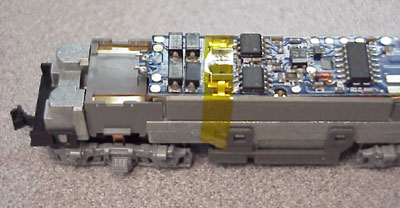
Test and program the loco. When you are satisfied that it is working, replace the shell. HINT: On a “B” unit, such as is shown in the photos, put the end of the shell with the road number toward the front of the decoder (the end closest to the motor tabs). That way you will always know which end of the loco the decoder considers “forward”.
Happy railroading!
Jeff Whitehorn